

From Bottom-Side Cooling to Top-Side Cooling: Structural Evolution in EV Power Systems
On-board chargers (OBCs), DC/DC converters, and inverters are typical high–power-density components in electric vehicles. As EV platforms evolve toward higher integration, lightweight design, and 800 V architectures, power output continues to increase while available installation space becomes increasingly constrained.
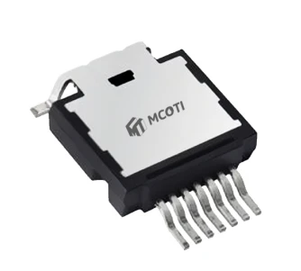
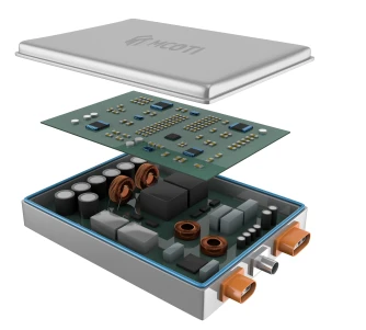
To reduce vehicle weight, extend driving range, and meet the requirements of next-generation high-voltage platforms, power devices are being pushed toward higher power density and smaller form factors. Under these conditions, the thermal management and electrical insulation design of power devices-such as MOSFETs-faces new challenges.
Why Top-Side Cooling Becomes the Preferred Choice for High Power Density
In conventional designs, most MOSFETs adopt Bottom-Side Cooling (BSC). The typical heat dissipation path is:
Die → Package bottom → Solder layer → PCB → Heatsink / Cold plate
In this configuration, heat is transferred through solder layers and thermal vias into the PCB, and then removed by a bottom-mounted heatsink or cold plate. This approach suffers from several inherent limitations:
► A long and complex thermal path, resulting in relatively high thermal resistance.
►The PCB bottom side must remain clear for thermal purposes, limiting component placement.
►Lower space utilization and increased overall PCB size.
In EV OBCs, DC/DC converters, and inverters, where power density continues to rise, these constraints increasingly limit system-level optimization.
As a result, TSC is becoming the mainstream architecture for next-generation power devices and power modules.
Key Advantages of Top-Side Cooling (TSC)
In a top-side cooling structure, the top surface of the MOSFET package is in direct contact with a heatsink or cold plate. The thermal path is simplified to:
Die → Package top → Heatsink / Cold plate
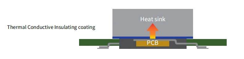
► Shorter thermal path and lower thermal resistance, as heat no longer needs to pass through the PCB
► Higher allowable power dissipation, especially under high transient power conditions
► Dual-sided PCB population, since the PCB bottom is no longer required for heat removal
► Improved system integration and automation compatibility, supporting compact and modular designs
► System-level efficiency and cost benefits, well suited for electrified and high-volume EV applications
New Challenges Under TSC: Thermal Conductive Insulation Coating
As power density continues to increase, interface materials must deliver faster thermal response, high-voltage insulation reliability, and manufacturing consistency.
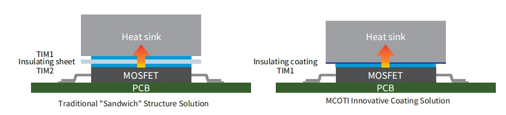
Traditionally, top-side cooling interfaces rely on a "TIM + insulation sheet + TIM" sandwich structure: TIM layers fill surface gaps and conduct heat. Insulation sheets provide high-voltage electrical isolation. While proven and reliable, this approach shows limitations in compact, high-power systems:
► Multiple interfaces slow down transient thermal response
►Assembly complexity increases, with tighter tolerance control
►BOM and manufacturing costs continue to rise
Against this background, thermal conductive insulation coatings are gaining attention as an integrated interface solution for top-side cooling architectures.
★ A single, continuous, thin, and uniform coating can simultaneously provide bonding, thermal conduction, and electrical insulation.
MCOTI MEP 37 Series: Thermally Conductive Insulating Coatings
To address the requirements of next-generation EV power systems and top-side cooled power devices, MCOTI has developed the MEP 37 series thermal conductive insulation coatings.
The MEP 37 series can be directly applied to heatsinks or metal baseplates. With an ultra-thin coating thickness of 100~250μm, it delivers dielectric withstand capability of 3,000~6,000V, forming a high-performance solution optimized for top-side cooling designs.
Key Benefits
● Interface integration: Replaces traditional insulation sheets with a single continuous coating, reducing interface count and shortening the thermal path
● Ultra-low thermal resistance: As low as 0.16 K·cm²/W, with excellent long-term thermal stability
● Automotive-grade reliability validation:
■ Damp heat: 1539H @ 85°C / 85% RH
■ Thermal shock: 790 cycles @ −40 to 125°C
■ High-temperature aging: 2000H @125°C
● Dielectric withstand voltage: 4.3 kV (all tests passed with consistent thermal performance)
System-level cost reduction: BOM analysis indicates approximately 40% material cost reduction, along with lower labor and assembly costs
● High process efficiency: Spray application with rapid curing enables short cycle times and high yield
● Scalable manufacturing: Compatible with automated spray processes, supporting volume production and process consistency
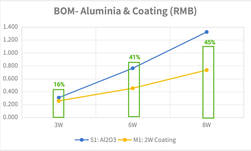
Chart 1: Comparison of Material Costs of MCOTI Coating Solutions with Traditional insulating Sheets
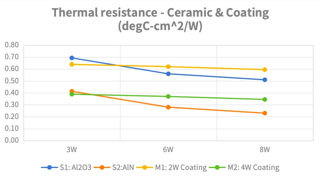
Chart 2: Comparison of Material Costs of MCOTI Coating Solutions with Traditional insulating Sheets


